July 4, 2026
Debugging an OV5647 device tree overlay on Raspberry Pi 4
A walkthrough of fixing a non-working camera overlay on Pi 4 — covering the missing fragments, I2C mux topology, clock setup, and how to verify the fix.
I recently needed to bring up an OV5647 camera module (the sensor used in the v1 Pi Camera) on a
Raspberry Pi 4 Model B running kernel 6.6.63 (custom Yocto Scarthgap build with core-image-base). The sensor was connected, the .dts overlay was
compiled and copied to /boot/overlays/, dtoverlay=ov5647 was set in config.txt, but after
reboot there was no /dev/video0 device and no camera driver in lsmod.
This post walks through the debugging process and what I had to fix.
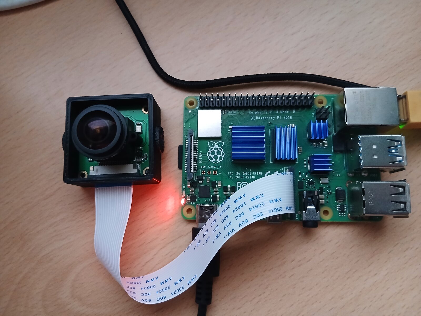
The overlay that did not work
Here is the overlay I started with proposal from ChatGPT - it looked reasonable at first glance:
/dts-v1/;
/plugin/;

{
    compatible = "brcm,bcm2835";

    fragment@0 {
        target = <&i2c_csi_dsi>;
        __overlay__ {
            status = "okay";
            #address-cells = <1>;
            #size-cells = <0>;

            cam_clk: cam_clk {
                compatible = "fixed-clock";
                #clock-cells = <0>;
                clock-frequency = <25000000>;
            };

            ov5647: ov5647@36 {
                compatible = "ovti,ov5647";
                reg = <0x36>;
                status = "okay";
                clocks = <&cam_clk>;
                clock-names = "xclk";
                rotation = <0>;
                orientation = <2>;
                port {
                    ov5647_ep: endpoint {
                        clock-lanes = <0>;
                        data-lanes = <1 2>;
                        clock-noncontinuous;
                        link-frequencies = /bits/ 64 <297000000>;
                        remote-endpoint = <&csi_ep>;
                    };
                };
            };
        };
    };

    fragment@1 {
        target = <&csi1>;
        __overlay__ {
            status = "okay";
            port {
                csi_ep: endpoint {
                    data-lanes = <1 2>;
                    clock-noncontinuous;
                    remote-endpoint = <&ov5647_ep>;
                };
            };
        };
    };

    fragment@2 {
        target = <&i2c0mux>;
        __overlay__ {
            status = "okay";
        };
    };
};
Three fragments: one to place the sensor on the I2C bus, one to configure the CSI receiver, and one to enable the I2C mux. Simple enough. But no camera appeared.
Finding out what is actually on the board
The first step was to check the real device tree the kernel was using at runtime.
# Show device tree symbol table entries for relevant nodes
for f in /proc/device-tree/__symbols__/*; do
  echo "$(basename $f): $(cat $f)"
done | grep -iE 'i2c|csi|cam|mux'
The output revealed the I2C topology on this Pi 4:
i2c0:      /soc/i2c0mux/i2c@0
i2c_csi_dsi:  /soc/i2c0mux/i2c@1
i2c_csi_dsi0: /soc/i2c0mux/i2c@0
i2c_vc:       /soc/i2c0mux/i2c@0
Wait — i2c_csi_dsi (the target my overlay used) points to i2c@1, and i2c_csi_dsi0 points to
i2c@0. I initially thought this was the bug: that my overlay was targeting the wrong bus.
The naming is confusing, but the Raspberry Pi 4 Model B has only one CSI camera port (the middle
connector, labelled CAMERA on the board). The SoC (BCM2711) has two CSI controllers internally,
but only CSI1 is routed to the physical connector on the Pi 4B. The corresponding I2C bus is
i2c_csi_dsi (i2c@1), which is shared with the DSI display output on that same connector.
The i2c_csi_dsi0 target and the cam0 overlay parameter exist for boards that expose both CSI
ports, such as the Compute Module 4 IO board (labelled CAM0 and CAM1). On a Pi 4B, the default
(cam1) is the only option.
So the I2C bus was correct — something else was wrong.
Comparing with the official overlay
I fetched the official overlay source from the Raspberry Pi kernel tree for 6.6.y:
// Fragment 0 — I2C bus with sensor
i2c_frag: fragment@0 {
    target = <&i2c_csi_dsi>;
    __overlay__ {
        #address-cells = <1>;
        #size-cells = <0>;
        status = "okay";
        #include "ov5647.dtsi"
    };
};

// Fragment 1 — CSI receiver
csi_frag: fragment@1 {
    target = <&csi1>;
    csi: __overlay__ {
        status = "okay";
        brcm,media-controller;
        port {
            csi_ep: endpoint {
                remote-endpoint = <&cam_endpoint>;
                data-lanes = <1 2>;
                clock-noncontinuous;
            };
        };
    };
};

// Fragment 2 — I2C0 interface controller
fragment@2 {
    target = <&i2c0if>;
    __overlay__ {
        status = "okay";
    };
};

// Fragment 3 — I2C mux
fragment@3 {
    target = <&i2c0mux>;
    __overlay__ {
        status = "okay";
    };
};

// Fragment 4 — regulator startup delay
reg_frag: fragment@4 {
    target = <&cam1_reg>;
    __overlay__ {
        startup-delay-us = <20000>;
    };
};

// Fragment 5 — camera clock
clk_frag: fragment@5 {
    target = <&cam1_clk>;
    __overlay__ {
        status = "okay";
        clock-frequency = <25000000>;
    };
};
The official overlay has six fragments, not three. The three I was missing explain exactly why nothing worked.
What the missing fragments do
fragment@2: i2c0if
The symbol i2c0if refers to the I2C controller at hardware level — the memory-mapped peripheral
that implements the I2C protocol on the BCM2711 SoC. Its register block lives at 0x7e205000.
On Pi 4, the physical I2C0 controller has multiple I2C buses routed through a mux
(i2c0mux). The mux selects between:
i2c@0— the VideoCore I2C bus (also calledi2c_vc), accessible as/dev/i2c-0i2c@1— the camera/display I2C bus (i2c_csi_dsi), accessible as/dev/i2c-10
If the underlying controller (i2c0if) is not enabled, neither child bus can operate. My overlay
enabled the mux (i2c0mux) but not the controller itself. That means the I2C transactions never
reached the sensor.
fragment@4: cam1_reg
cam1_reg is a fixed regulator that controls the 1.8V power rail to the camera connector via GPIO
- The base device tree defines it as:
cam1_reg: cam1_regulator {
    compatible = "regulator-fixed";
    regulator-name = "cam1-reg";
    enable-active-high;
    gpio = <&gpio 5 0>;
};
The regulator is present in the base DT but without a startup delay. The overlay adds:
startup-delay-us = <20000>;
This gives the sensor 20 ms to power up and stabilise before the kernel attempts I2C communication. Without this delay, the sensor might not be ready when the driver tries to probe it.
fragment@5: cam1_clk
The OV5647 needs a 24 or 25 MHz clock input (XCLK). The base DT has a cam1_clk node (a fixed
clock generator), but it is disabled by default and has no frequency set:
$ cat /proc/device-tree/cam1_clk/status
disabled
$ ls /proc/device-tree/cam1_clk/clock-frequency
ls: clock-frequency: No such file or directory
My overlay defined a clock inline as a child of the I2C bus node:
cam_clk: cam_clk {
    compatible = "fixed-clock";
    #clock-cells = <0>;
    clock-frequency = <25000000>;
};
This is invalid. A fixed-clock describes a hardware oscillator — it must live at the root of the
device tree, not as a child of an I2C peripheral. The kernel’s clock framework ignores it.
The official overlay fixes this by referencing the existing cam1_clk node and enabling it with
the correct frequency:
clk_frag: fragment@5 {
    target = <&cam1_clk>;
    __overlay__ {
        status = "okay";
        clock-frequency = <25000000>;
    };
};
The fixed overlay
Here is the corrected version, matching the official overlay structure:
// SPDX-License-Identifier: GPL-2.0-only
/dts-v1/;
/plugin/;

/{
    compatible = "brcm,bcm2835";

    i2c_frag: fragment@0 {
        target = <&i2c_csi_dsi>;
        __overlay__ {
            #address-cells = <1>;
            #size-cells = <0>;
            status = "okay";

            cam_node: ov5647@36 {
                compatible = "ovti,ov5647";
                reg = <0x36>;
                status = "okay";

                clocks = <&cam1_clk>;
                clock-names = "xclk";

                avdd-supply  = <&cam1_reg>;
                dovdd-supply = <&cam_dummy_reg>;
                dvdd-supply  = <&cam_dummy_reg>;

                rotation = <0>;
                orientation = <2>;

                port {
                    cam_endpoint: endpoint {
                        clock-lanes = <0>;
                        data-lanes = <1 2>;
                        clock-noncontinuous;
                        link-frequencies = /bits/ 64 <297000000>;
                    };
                };
            };
        };
    };

    csi_frag: fragment@1 {
        target = <&csi1>;
        csi: __overlay__ {
            status = "okay";
            brcm,media-controller;

            port {
                csi_ep: endpoint {
                    remote-endpoint = <&cam_endpoint>;
                    data-lanes = <1 2>;
                    clock-noncontinuous;
                };
            };
        };
    };

    fragment@2 {
        target = <&i2c0if>;
        __overlay__ {
            status = "okay";
        };
    };

    fragment@3 {
        target = <&i2c0mux>;
        __overlay__ {
            status = "okay";
        };
    };

    reg_frag: fragment@4 {
        target = <&cam1_reg>;
        __overlay__ {
            startup-delay-us = <20000>;
        };
    };

    clk_frag: fragment@5 {
        target = <&cam1_clk>;
        __overlay__ {
            status = "okay";
            clock-frequency = <25000000>;
        };
    };
};

&cam_node {
    status = "okay";
};

&cam_endpoint {
    remote-endpoint = <&csi_ep>;
};
Note the regulator supplies: avdd-supply, dovdd-supply, and dvdd-supply. The Pi’s cam1_reg
(GPIO 5) switches the 1.8V rail that powers the camera connector. The camera module then uses
on-board regulators to derive AVDD (2.8V) and DVDD (1.5V) from the 3.3V input on the connector.
The driver expects all three supply bindings to be present, so cam_dummy_reg (a fixed always-on
regulator) is assigned to dovdd-supply and dvdd-supply. The real cam1_reg is mapped to
avdd-supply — not because it supplies 2.8V directly, but because the driver only needs to ensure
GPIO 5 is asserted for the module to receive power. The bindings are about the enable sequence, not
voltage accuracy.
How to verify the fix
After copying the compiled ov5647.dtbo to /boot/overlays/ and rebooting:
# Check I2C detection — 'UU' means driver is active
$ i2cdetect -y 10
     0  1  2  3  4  5  6  7  8  9  a  b  c  d  e  f
00:                         -- -- -- -- -- -- -- --
10: -- -- -- -- -- -- -- -- -- -- -- -- -- -- -- --
20: -- -- -- -- -- -- -- -- -- -- -- -- -- -- -- --
30: -- -- -- -- -- -- UU -- -- -- -- -- -- -- -- --
40: -- -- -- -- -- -- -- -- -- -- -- -- -- -- -- --
50: -- -- -- -- -- -- -- -- -- -- -- -- -- -- -- --
60: -- -- -- -- -- -- -- -- -- -- -- -- -- -- -- --
70: -- -- -- -- -- -- -- --

# Verify modules are loaded
$ lsmod | grep -E 'unicam|ov5647'
bcm2835_unicam  53248  0
ov5647          20480  1

# Find the video device
$ ls /dev/video0
/dev/video0

# Check the media pipeline
$ media-ctl -d /dev/media4 -p
# Shows ov5647 10-0036 -> unicam-image pipeline

# Capture a test frame
$ v4l2-ctl -d /dev/video0 \
    --set-fmt-video=width=640,height=480,pixelformat=GB10 \
    --stream-mmap --stream-to=test.raw --stream-count=5

$ ls -la test.raw
-rw-r--r-- 614400  # 5 * 640 * 480 * 2 bytes
Summary of the issues
| Issue | Symptom | Fix |
|---|---|---|
Missing i2c0if fragment |
I2C bus never operational, sensor invisible | Enable the I2C controller peripheral |
Missing cam1_reg fragment |
Regulator enables GPIO 5 with no startup delay | Add 20 ms startup delay |
Missing cam1_clk fragment |
25 MHz clock disabled and unconfigured | Enable and set clock-frequency |
Inline fixed-clock as I2C child |
Clock ignored by clock framework | Reference &cam1_clk instead |
The core lesson: a device tree overlay must enable every link in the hardware chain — not just the final device, but also the controllers, clocks, and regulators that the device depends on. Each is a separate fragment that references the relevant node.
license: CC BY 4.0