July 9, 2026
Bringing Zephyr RTOS to an ESP32 board
A compact first bring-up of Zephyr on ESP32, from hello world to fixing the blinky sample with a device tree overlay.
Zephyr is a good fit when you want an RTOS with a modern embedded workflow: reproducible builds, board descriptions, Kconfig-based configuration, device tree hardware modelling, and a large set of samples that are useful for bring-up. On ESP32, it also gives you a path outside the usual ESP-IDF-only workflow while still using Espressif-supported hardware.
I followed Espressif’s Zephyr RTOS on ESP32 – First Steps
guide to get the basic environment running. The first milestone was simple: build and flash
samples/hello_world. After that worked, I moved to samples/basic/blinky, which is where the
interesting part started.
I bought two inexpensive ESP32 boards on Amazon. The board I used is most likely an ESP32 DevKitC-style clone, probably sold under the QIQIAZI name. That matters because clones usually follow the same general ESP32 DevKit pinout, but small details such as the connected user LED can differ. Espressif’s ESP32-DevKitC user guide and its header block / pinout section are the best reference points for the board shape. For the module itself, the closest datasheet is Espressif’s ESP32-WROOM-32 datasheet.
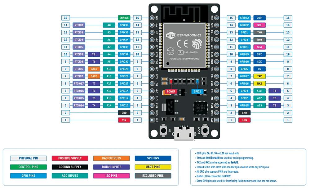
Why Zephyr feels different
If you come from bare-metal projects or vendor SDKs, Zephyr can feel indirect at first. A simple LED blink is not just “write to GPIO 2”. The application asks Zephyr for a device described by the board’s hardware model, and Zephyr wires the driver, pin, GPIO controller, and flags together during the build.
That indirection is the point. The same application can run on different boards because the board specific details live in device tree and configuration files instead of being scattered through application code.
The main pieces are:
west: Zephyr’s workspace and build tool- Kconfig: compile-time feature and driver configuration
- device tree: hardware description consumed at build time
- board definitions: CPU, memory, peripherals, pins, and aliases for a specific target
- samples: small applications that exercise one Zephyr feature at a time
For bring-up, the practical loop is:
west build -p always -b <your_esp32_board> samples/hello_world
west flash
west espressif monitor
Once serial output shows the hello world message, the toolchain, board target, flashing, and monitor path are working.
Identifying the board
Before going further, I checked what the connected chip reports:
esptool chip-id
The output was:
Chip type:          ESP32-D0WD-V3 (revision v3.1)
Features:           Wi-Fi, BT, Dual Core + LP Core, 240MHz,
                    Vref calibration in eFuse, Coding Scheme None
Crystal frequency:  40MHz
This identifies the SoC as an ESP32-D0WD-V3. In practical terms, this is the classic dual-core ESP32 family: Wi-Fi, Bluetooth, 240 MHz CPU, and a 40 MHz crystal on this board. That matches the kind of module commonly found on ESP32-WROOM-32 / ESP32 DevKitC-style boards.
The exact development board is harder to identify from software alone. Mine appears to be a DevKitC-compatible clone, probably QIQIAZI-branded. For Zephyr, that is usually fine as long as the board target matches the ESP32 family and any board-specific differences, such as the LED GPIO, are described with an overlay.
From hello world to blinky
The next sample I tried was the basic blinky application:
west build -p always -b <your_esp32_board> samples/basic/blinky
This failed during compilation with an error starting like this:
error: '__device_dts_ord_DT_N_ALIAS_led0_P_gpios_IDX_0_PH_ORD' undeclared here
The error looks cryptic, but the cause is simple: the blinky sample expects a device tree alias
named led0.
In Zephyr’s blinky sample, the LED is usually obtained from something equivalent to:
GPIO_DT_SPEC_GET(DT_ALIAS(led0), gpios)
The relevant source code is small:
#include <stdio.h>
#include <zephyr/kernel.h>
#include <zephyr/drivers/gpio.h>

/* 1000 msec = 1 sec */
#define SLEEP_TIME_MS 1000

/* The devicetree node identifier for the "led0" alias. */
#define LED0_NODE DT_ALIAS(led0)

/*
 * A build error on this line means your board is unsupported.
 * See the sample documentation for information on how to fix this.
 */
static const struct gpio_dt_spec led = GPIO_DT_SPEC_GET(LED0_NODE, gpios);

int main(void)
{
    int ret;
    bool led_state = true;

    if (!gpio_is_ready_dt(&led)) {
        return 0;
    }

    ret = gpio_pin_configure_dt(&led, GPIO_OUTPUT_ACTIVE);
    if (ret < 0) {
        return 0;
    }

    while (1) {
        ret = gpio_pin_toggle_dt(&led);
        if (ret < 0) {
            return 0;
        }

        led_state = !led_state;
        printf("LED state: %s\n", led_state ? "ON" : "OFF");
        k_msleep(SLEEP_TIME_MS);
    }
}
That means the application is not asking for a hard-coded GPIO number. It is asking the board
description: “What is led0 on this board?”
On many ESP32 development boards there is no LED defined in Zephyr’s board device tree, and some
DevKit boards do not have a user LED at all. So the build cannot resolve led0, and the generated
device symbol is missing.
Fixing it with a device tree overlay
The fix is to provide the missing hardware description with an overlay. For my board, the LED was on GPIO2, so I added this overlay:
#include <zephyr/dt-bindings/gpio/gpio.h>

/ {
    aliases {
        led0 = &user_led;
    };

    leds {
        compatible = "gpio-leds";

        user_led: led_0 {
            gpios = <&gpio0 2 GPIO_ACTIVE_HIGH>;
            label = "User LED";
        };
    };
};
There are two important parts here.
First, this creates a gpio-leds node. That tells Zephyr this is a GPIO-controlled LED and gives it
the GPIO controller, pin number, and active level:
gpios = <&gpio0 2 GPIO_ACTIVE_HIGH>;
Second, it creates the alias expected by the sample:
led0 = &user_led;
After that, the blinky sample has a concrete device tree node to bind to.
For a quick experiment inside the Zephyr tree, one simple option is to place the overlay as:
zephyr/samples/basic/blinky/app.overlay
Then rebuild from the workspace:
west build -p always -b <your_esp32_board> zephyr/samples/basic/blinky
west flash
west espressif monitor
If your board uses a different LED pin, change the 2 in the gpios property. GPIO2 is common on
some ESP32 dev boards, but it is not universal.
What device tree is doing here
Device tree is a hardware description language. In Zephyr, it is processed at build time and turned into generated C macros and metadata. Application code and drivers then use those generated symbols instead of parsing device tree at runtime.
That explains why a missing led0 alias appears as a compile-time error instead of a runtime
failure. The application requested a hardware object that does not exist in the final device tree.
Zephyr catches that while compiling.
A useful mental model is:
- device tree says what hardware exists
- Kconfig says which software features and drivers are enabled
- application code asks for hardware by node, alias, or compatible string
- the build system connects those pieces before the firmware is produced
This is also why overlays are so useful. You do not need to fork the board definition for every small hardware difference. If your carrier board, dev board revision, or breadboard wiring differs, an overlay can describe just that difference.
Lessons from the first bring-up
The hello world sample proves the basic ESP32 Zephyr setup: toolchain, board target, flashing, and UART monitor. The blinky sample proves something different: whether the board description contains the hardware abstraction the application expects.
The failure was not really a GPIO driver problem. It was a device tree problem:
blinky expects led0 -> board device tree has no led0 -> build fails
Once the overlay defined led0, the sample built normally and the LED blinked.
That is a useful first Zephyr lesson. When a sample fails with generated device tree symbol names, look for the node or alias the sample expects. In many cases the fix is not in C code at all; it is in the board description.
For ESP32 bring-up, I would keep the first path small:
- build and flash
samples/hello_world - verify serial output with
west espressif monitor - build
samples/basic/blinky - add an overlay if the board has no
led0alias - only then move on to Wi-Fi, Bluetooth, storage, or bootloader work
That sequence keeps the early debugging focused. First prove the toolchain and flashing path, then prove the hardware description model, and only then start testing the more complex peripherals.
license: CC BY 4.0